Hello, this is VALVEPARK.
Vacuum systems are mission-critical equipment across a wide range of industries - semiconductors, displays, secondary batteries, research instruments, and more.
Using the diagram in this article as a reference, today we will walk through the structure and operating principle of a vacuum system in plain language.
(Vacuum System)
A vacuum system is equipment that lowers the pressure inside a chamber below atmospheric pressure so that a process can be carried out.
It removes unwanted gases and precisely controls only the desired gases, allowing the process to run reliably.
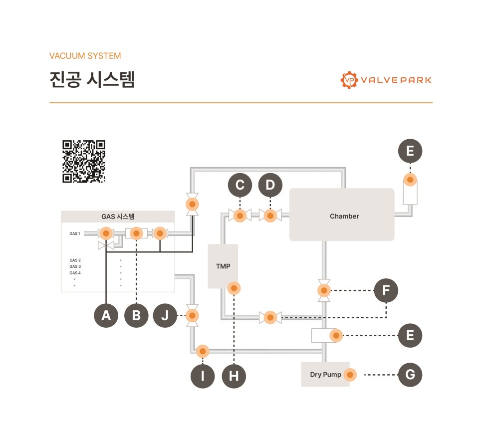
• GAS system
• Chamber
• TMP (turbo-molecular pump)
• Dry Pump
• Various valves and sensors (labeled A - J)
We'll explain step by step in process order.
Multiple gas lines are connected.
• GAS 1 ~ GAS 4
• Gas shut-off valves
• Gas control valves
• Gas-supply control section
• Flow rate is regulated by manual or automatic valves
• Only the gases required by the process are selectively supplied
This section delivers process gases at the correct pressure and flow rate.
This is the space where the actual process takes place.
• Wafer deposition
• Etching
• Coating
• Experiments
This section delivers process gases at the correct pressure and flow rate.
The TMP at the center is the core device that creates high vacuum.
H location
• Pressure sensing tied to the TMP
• Monitors pressure in the high-vacuum region
Characteristics
• Pumps gas molecule by molecule
• Builds high vacuum
• Essential equipment in semiconductor tools
The dry pump (roughing pump) at the bottom plays the following roles.
G location
• Dry-pump monitoring point
Roles
• Initial evacuation (roughing stage)
• Backing pump for the TMP
• Lowers pressure from atmospheric down into the medium-vacuum range
💡 Typical sequence
1️⃣ Start the dry pump
2️⃣ Reach a target pressure
3️⃣ Start the TMP
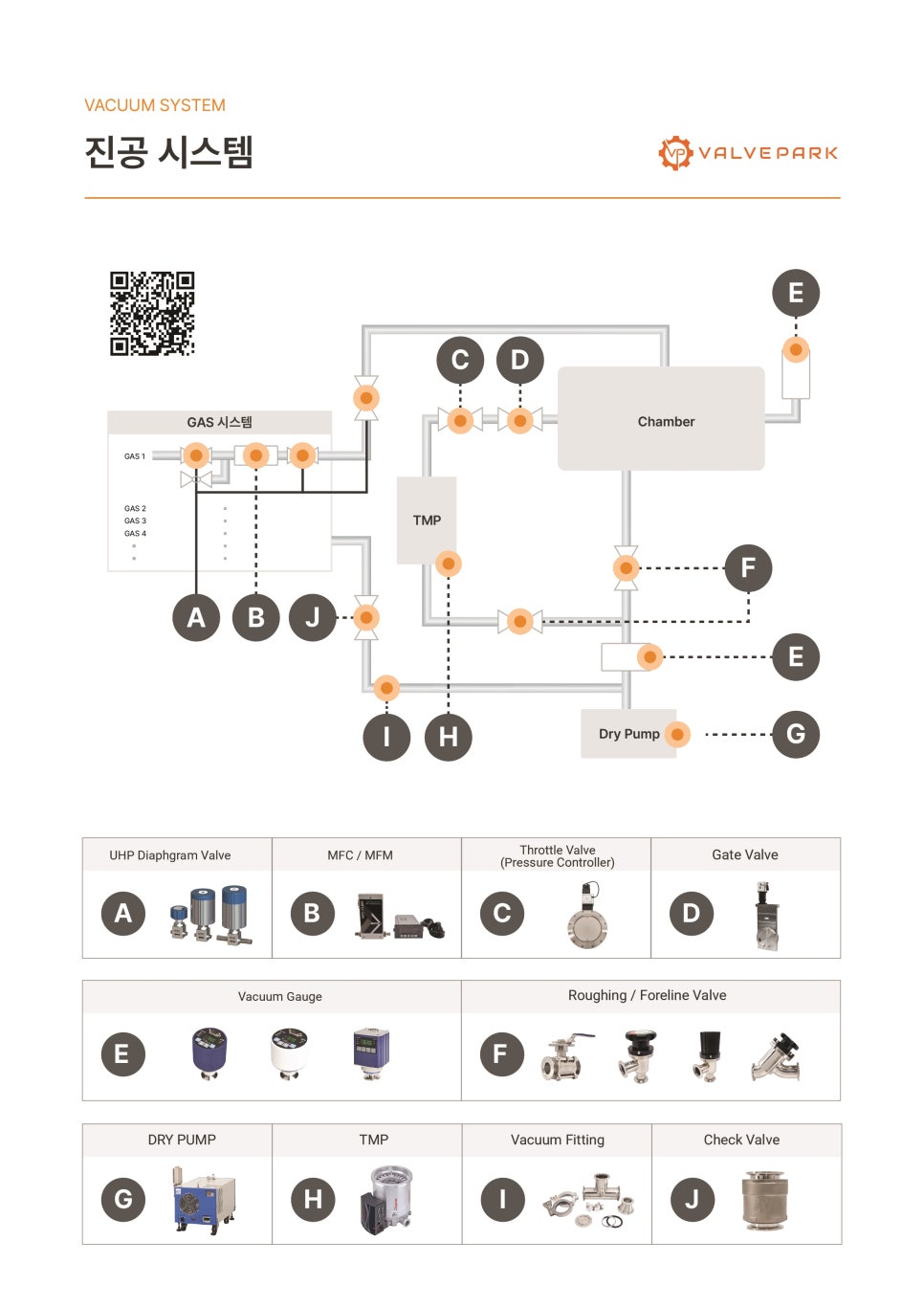
| Label | Roles |
|---|---|
| A | Gas shut-off valve |
| B | Gas-supply control |
| C, D | Chamber isolation valve |
| E | Exhaust-line control |
| F | Pressure sensor |
| G | Dry-pump status monitoring |
| H | TMP pressure sensing |
| I | Roughing-line control |
| J | Exhaust-direction switching |
1. Close all gas valves
2. Start the dry pump
3. Open the roughing valve
4. Reach medium vacuum
5. Start the TMP
6. Establish high vacuum in the chamber
7. Inject process gas
8. Control pressure and run the process
A vacuum system is not just a pump -
it is a precision installation that integrates gas control, pressure control, and safety design as one organic whole.
When the staged TMP - dry-pump architecture and the role of each valve (A - J) are understood correctly,
response capability for equipment troubles is also greatly improved.
Going forward, VALVEPARK will continue to share information on industrial equipment and automation systems
in a clearer and more accessible way.
VALVEPARK - Everything for Industrial Valves
Industrial valve solutions made simple and fast! Experience every industrial valve and expert technical solution one-stop, without on-site visits!
www.valvepark.com