Class I to VI: grades that set the allowable control valve seat leakage by air or water testing
Helium leak rate: a value in mbar·L/s that has meaning only when the test gas and the pressures on both sides are defined
Conversion: Class and mbar·L/s are not converted into each other; only conversion between units is possible
What to check: the type of criterion, the value, the test gas, the differential pressure, and whether it is seat or external leakage
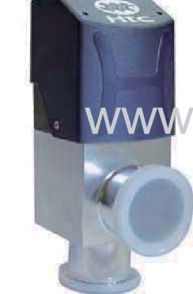
Configurations: HTC aluminum block angle valve, bellows-seal angle valve that has passed a helium leak test, HTC bakeable all-metal valve, HTC pendulum valve
Hello, this is VALVEPARK.
Class I to VI are grades that set, by testing with air or water, the allowable amount that leaks through the seat when a control valve is closed. The mbar·L/s in a vacuum specification is usually a leak rate measured with helium, and because the test gas, differential pressure and units differ, a value from one side is not carried over to the other.
When a specification lists both "leakage Class IV" and "1×10⁻⁹ mbar·L/s", first sort out which valve and which leak each value refers to. Only with this distinction can the quotation conditions be set.
They are grades that divide the allowable amount leaking past the seat of a closed control valve into six levels. They are defined in the FCI 70-2 standard (formerly ANSI B16.104), and the test medium is air or water.
Class II to IV set the allowable leakage as a ratio to the valve's rated flow (maximum Cv) and are tested at a differential pressure of about 45 to 60 psi. Class V sets a value proportional to seat diameter and differential pressure, with water as the basis. Class VI sets the leakage per minute by seat diameter (number of bubbles) at a differential pressure of about 50 psi with air or nitrogen.
| Class | Allowable leakage | Test medium |
|---|---|---|
| I | No test, agreed between user and manufacturer | Agreed |
| II | 0.5% of rated flow | Air or water |
| III | 0.1% of rated flow | Air or water |
| IV | 0.01% of rated flow | Air or water |
| V | Water 0.0005 mL/min × seat diameter (inch) × differential pressure (psi) | Water |
| VI | Leakage per minute by seat diameter; for a 2-inch seat, 0.45 mL/min (3 bubbles/min) | Air or nitrogen |
Class I: no test, agreed between user and manufacturer
Class II: 0.5% of rated flow, air or water
Class III: 0.1% of rated flow, air or water
Class IV: 0.01% of rated flow, air or water
Class V: water 0.0005 mL/min × seat diameter (inch) × differential pressure (psi)
Class VI: leakage per minute by seat diameter; for a 2-inch seat, 0.45 mL/min (3 bubbles/min), air or nitrogen
Class VI is a grade used for soft-seat valves, usually met with a rubber or plastic seat. The "Class" in a specification can also mean a pressure rating such as Class 150, so first check whether it is written in Roman numerals I to VI.
A seat leakage grade measured with air or water
The value has meaning only when the test gas and the pressures on both sides are defined. The helium standard condition common in practice uses helium with one side at atmospheric pressure and the other side at a vacuum below 1 mbar, applying a differential pressure of about 1 bar.
mbar·L/s is the amount that leaks in per unit time, expressed as pressure times volume. For parts used in vacuum, it is desirable to test by the vacuum method, in which the inside of the sample is pumped down and helium is applied outside, the same as in actual use. A helium detector finds even small leaks at the level of 10⁻¹² mbar·L/s. The sniffer method, which pressurizes the sample and scans with a probe, reaches only about 10⁻⁷ mbar·L/s, so a 10⁻⁹ specification is confirmed by the vacuum method.
The HTC pendulum valve catalog states this condition as "helium leak rate at 1 atm differential pressure". The aluminum body is divided into less than 1×10⁻⁹ mbar·L/s, and the hard anodized body into less than 1×10⁻⁵ mbar·L/s. The same valve differs by four orders of magnitude depending on the body surface, so look at the value together with the test condition.
A leak rate includes the test gas and the differential pressure
No, they are not converted. The test gases differ: air and water versus helium. The differential pressures differ: a pressurized test of about 45 to 60 psi vented to atmosphere versus a test of about 1 bar applied toward the vacuum side. The units of the values also differ: a ratio of rated flow or mL/min versus mbar·L/s.
Converting a helium value to an air value cannot be fixed by one number either, because the equations differ between laminar and molecular flow. A leak rate larger than about 10⁻⁵ mbar·L/s is treated as laminar flow and one smaller than about 10⁻⁷ mbar·L/s as molecular flow, and in between the manufacturer assumes a value on the safe side.
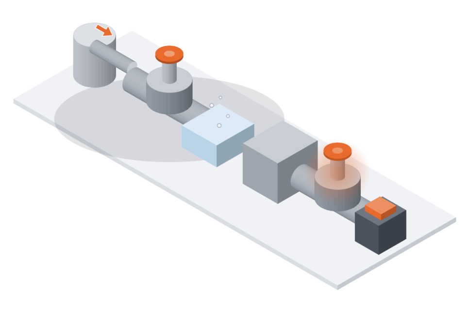
On the left, a test that pressurizes with air and watches for bubbles in water; on the right, a test that pumps one side down to a vacuum, applies helium outside and reads a detector
The bubble test has the same problem. Per the catalog, the expression "no bubbles are seen" has no meaning unless the leak rate is defined. It states that a leak that shows no bubbles in soap solution is below 1×10⁻³ to 1×10⁻⁴ cc/s. This is a different order of magnitude from the leaks a helium detector finds.
| Comparison item | Seat leakage Class I to VI | Helium leak rate |
|---|---|---|
| What it defines | Allowable leakage through the seat when a control valve is closed | Amount of helium leaking into the sample |
| Test gas | Air or water (air or nitrogen for Class VI) | Helium |
| Test pressure | II to IV about 45 to 60 psi, VI about 50 psi, toward atmosphere | One side atmospheric, the other below 1 mbar (about 1 bar differential) |
| Form of the value | % of rated flow, mL/min, number of bubbles | mbar·L/s (example: 1×10⁻⁹) |
| Where it mainly appears | Control valve and process piping specifications | Vacuum valve and chamber/exhaust line specifications |
What it defines: Class is the allowable leakage through the seat when a control valve is closed; helium leak rate is the amount of helium leaking into the sample
Test gas: Class uses air or water (air or nitrogen for Class VI); helium leak rate uses helium
Test pressure: Class uses about 45 to 60 psi for II to IV and about 50 psi for VI toward atmosphere; helium leak rate uses atmospheric pressure on one side and below 1 mbar on the other (about 1 bar differential)
Form of the value: Class is % of rated flow, mL/min or number of bubbles; helium leak rate is mbar·L/s (example: 1×10⁻⁹)
Where it mainly appears: Class appears in control valve and process piping specifications; helium leak rate in vacuum valve and chamber/exhaust line specifications
Where the leak occurs also differs by criterion. Class I to VI look only at the amount leaking from inlet to outlet past the seat of a closed valve. The helium leak rate in a vacuum specification can refer to the seat side, the external side where atmosphere gets in through the stem seal and body joints, or the total of the two.
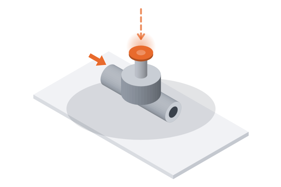
A solid arrow passing through the valve and a dotted arrow entering from outside at the stem
Seat leakage and external leakage are separate
If the specification gives a helium leak rate, choose from vacuum valves; if it gives a Class, confirm which valve the requirement is attached to before configuring. We listen to the type of criterion and the test conditions, then sort out the matching criterion and valve to suggest.
| 1×10⁻⁹ class leak rate, KF16 to KF40 automatic shut-off | HTC aluminum block angle valve Leak rate 1×10⁻⁹ mbar·L/s, operating pressure 1×10⁻⁸ mbar to 2 bar |
| Roughing and foreline with helium testing | VALVEPARK vacuum pneumatic angle valve (SUS304, single acting, bellows seal) Helium leak test before shipment |
| Ultra-high vacuum and high-temperature bakeout | HTC bakeable all-metal valve Leak rate 5×10⁻¹⁰ mbar·L/s, bakeout at 400℃ open |
| Chamber pressure control, ISO 200 to 320 | HTC pendulum valve Helium leak rate divided by body surface |
HTC aluminum block angle valve: 1×10⁻⁹ mbar·L/s class leak rate, KF16 to KF40
An aluminum block type angle valve used on lines that need small-bore automatic shut-off, such as gas isolation, vent and process gas control. Per the catalog, the leak rate is 1×10⁻⁹ mbar·L/s and the operating pressure is 1×10⁻⁸ mbar to 2 bar, with a normally closed construction that opens by air pressure and closes by spring.
Composition: 6061-T6 aluminum body (stainless steel on request), 316Ti stainless steel bellows and valve plate, Viton seal
Connection and actuation: KF16, KF25 and KF40, pneumatic 4 to 6 kg/cm², no restriction on mounting orientation or flow direction
Differential pressure: 5 bar in the closing direction, 2 bar in the opening direction
Indication and maintenance: electrical and LED position indication; loosen the 4 bolts under the cover to replace the bellows and seal
Life: 10 million cycles (room temperature 25℃, clean environment, differential pressure below 10 mbar when opening)
The all-in-one standard type puts the solenoid and microswitch in the top cover and connects them with a quick connector. Bakeout is up to 80℃ for the aluminum body, so it is not suited to lines baked at higher temperatures.
VALVEPARK vacuum pneumatic angle valve (SUS304, single acting, bellows seal): helium leak test before shipment
An angle valve used at automatic shut-off points that separate atmosphere from vacuum, such as roughing and foreline. A metal bellows surrounds the valve shaft to separate atmosphere from vacuum, and because it passes a helium leak test before shipment, the test gas is the same as the helium leak rate in the specification.
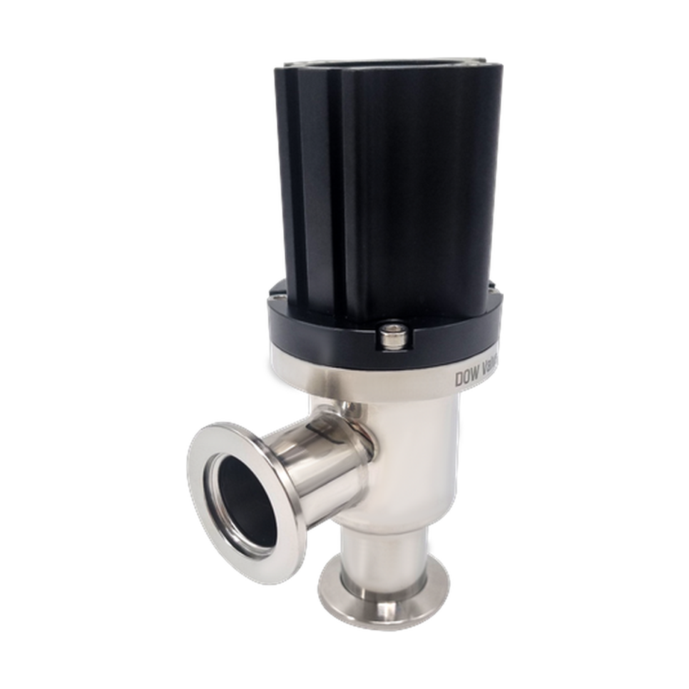
An angle valve showing two KF flanges and the pneumatic cylinder on top
Composition: SUS304 body, bellows seal, pneumatic single acting
Fail-safe action: when air pressure is lost, a spring returns the valve to a set direction (closed or open), and the direction is set by specification
Test: helium leak test before shipment
HTC bakeable all-metal valve: 5×10⁻¹⁰ mbar·L/s leak rate, ultra-high vacuum bakeout lines
For the high bakeout temperatures and low leak rates of ultra-high vacuum piping, an all-stainless steel valve is used. Per the catalog, the leak rate is 5×10⁻¹⁰ mbar·L/s and the operating pressure is 1×10⁻¹⁰ mbar to 1000 mbar. The bakeout temperature is 400℃ open and 300℃ closed.
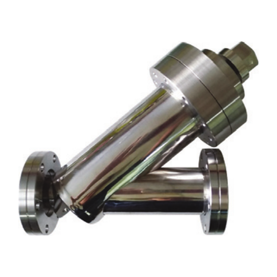
An in-line all-metal valve with both flanges facing the same direction and the actuator standing at an angle
Construction: all-stainless steel construction, bellows stem seal, no restriction on mounting orientation
Types and sizes: angle and straight-through, in three sizes CR16, CR35 and CR63
Bakeout: values are divided by state, 400℃ open and 300℃ closed, so they can be checked one by one against the bakeout conditions in the specification
For general vacuum piping with no bakeout or a low one, an all-metal valve is often not needed.
HTC pendulum valve: helium leak rate divided by body surface
Used at the throttle position between a chamber of ISO 200, 250 and 320 sizes and a turbomolecular pump, and driven pneumatically, in 3-position or APC mode. The catalog states the leak rate on a helium basis at 1 atm differential pressure and divides the values by body surface.
Aluminum body: less than 1×10⁻⁹ mbar·L/s, operating pressure 1×10⁻⁸ mbar to 1.2 bar
Hard anodized body: less than 1×10⁻⁵ mbar·L/s, operating pressure 1×10⁻⁶ mbar to 1.2 bar
Common: maximum differential pressure 1.2 bar, differential pressure of 5 mbar or less when opening, bakeout of the body at 120℃ or below
The hard anodized body has a larger leak rate value and a higher lower limit of operating pressure, so for ultra-high vacuum specifications check the aluminum body.
Match the valve and the test conditions together to the specification criterion
Q. If a specification lists both Class IV and 1×10⁻⁹ mbar·L/s, which one is the criterion for this valve?
It is sorted by what the valve does. For a control valve that regulates or shuts off a process fluid, Class is often applied, and for a vacuum valve that separates a vacuum chamber from an exhaust line, helium leak rate is often applied. If both values are written for one valve, they are separate test items, so confirm with the specification author which leak of which valve each refers to.
Q. What should I do if the test gas and differential pressure are not stated with the leak rate?
Do not assume it is the helium standard condition (helium, about 1 bar differential pressure); confirm the conditions with the specification author. Even with the same value, a different gas and differential pressure make it a different test, so quoting without knowing the conditions can change the acceptance criterion later.
Q. Can ISO 15848-1, an external leakage standard, also be required for vacuum valves?
That standard excludes vacuum applications from its scope, so it does not fit a vacuum valve specification as is. ISO 15848-1 (a type test standard for external leakage at the stem and body joints) sets grades AH, BH and CH in mbar·L/s per 1 mm of stem diameter. For a vacuum valve, check in the specification whether the helium leak rate is the seat, the external or the total.
Q. What if the leak rate is written in atm·cc/s or Pa·m³/s?
Unit conversion is possible. 1 mbar·L/s is about 0.987 atm·cm³/s, about 0.1 Pa·m³/s and about 0.75 Torr·L/s. This is a conversion between units for values under the same test conditions, and changing units does not make a Class value measured with air or water a substitute for a helium leak rate specification.
If you tell us the type and value of the leakage criterion, the test gas and differential pressure, and the valve type and size, we can start a specification review.
1️⃣ Type of criterion: whether it is Class (I to VI), helium leak rate or an external leakage standard
2️⃣ Value and unit: for example Class IV, 1×10⁻⁹ mbar·L/s, atm·cc/s
3️⃣ Test conditions: test gas, differential pressure, and whether it is seat, external or total
4️⃣ Valve type and size: angle, in-line, pendulum, and connection standard (KF, ISO, CF)
5️⃣ Operating pressure and temperature: vacuum level, bakeout temperature, and open and closed states
6️⃣ Quantity and desired delivery date
Please contact us if you need a specification sheet or detailed materials.
▸ View product: HTC aluminum block angle valve
▸ See also: HTC bakeable all-metal valve
Purchase and Inquiries
| sales@valvepark.com | |
| Phone | 1666-0215 |
| KakaoTalk channel | KakaoTalk consultation |
| Website | Go to the VALVEPARK website |
| Smart Store | Go to the VALVEPARK Smart Store |